Part 3
Previously ….
“Generally, people install Lead Acid Batteries in their Recreational Vehicles and Boats to run the everyday Habitation/House services. But there is increased interest in Lithium Batteries (and particularly the LiFePO4 style of Lithium) as they offer various benefits and advantages over Lead – however up-front cost is definitely not one!
But what about the idea of using both at the same time, maybe taking advantage of both Lead and Lithium at the same time? Wouldn’t that be cool if it were possible? Well, maybe it is ….”
The Previous Pages discussed the theory behind having Lithium and Lead running – and physically connected – together. And then we went into some details using charts of what happens in practice.
In this 3rd Part, we are going to consider how to charge a Lithium Battery Bank and a Lead Acid Bank when they are combined into one Hybrid setup.
Please Note: The content here is provided as general advice and information and is not specific to YOU or YOUR vehicle.
It should be used at your risk, is not warranted or guaranteed in any way and we are not liable for any losses or damage that might occur.
If this is not acceptable to you and you do not agree to this, do not read any further.
Charging Considerations
Lithium Batteries and Lead Acid have different charging requirements and characteristics, so how does it work with Lead and Lithium cabled together?
Well, many LifePO4 Batteries are specified as “Drop In” replacements for a Lead Acid battery so that means that voltage requirements are similar – but they are still not the same really, so some thought must go into how to setup your chargers.
The typical LiFePO4 battery ideally wants a charge voltage around 14.2V and a float of around 13.6V is quoted (different manufacturers will specify their own parameters, but those are pretty typical. In reality, NO float is preferred, but most chargers need a float voltage specified). The Typical Lead Acid wants around 14.4V to 14.7V and a float around 13.8V – so you can see a gap there.
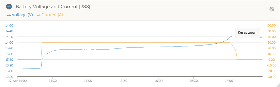
The other aspect of charging is the charging time and duration the charger stays at the high charge voltage before switching to Float. Lead Acid Batteries have a duration of between 5-8 Hours where they can sit at the 14.xV voltage before they should go to Float. LiFePO4 Batteries generally only hit 14.2V as they get to the end of their charge and then want no more. The graph below shows the LiFePO4 battery I have and its charge pattern on a 30A charger – takes full current until nearly full and then the voltage increases to finish the job and the current drops away to zero.
With the Lead -Lithium mix however, the LiFePO4 battery will be presented with the 14.xV voltage for potentially many hours if the Lead Bank got some good use (as in our example here where we took 110Ah out the bank) and needs recharging.
The chart below shows the final stage of the Lithium Recharge. It is quite intriging that the voltage line above for the standalone Lithium Charging with a 30A charger is virtually identical to the line below with the Hybrid Bank and a 70A charger. The similarity of course is that it the Lithium battery in the Hybrid pack that is getting the lions share of the charge.
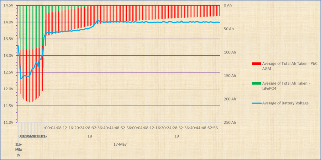
So as mentioned, you see the same kind of voltage pattern as the previous charging chart, where the voltage is under 14V and then as the final current goes in around 30 minutes past the hour the voltage goes up. We then have it staying high (above 14V) due to the Lead Acid batteries much slower charge at the top 20% or so. And it is this behaviour that can be a potential cause of concern which we will touch on shortly.
Note that I didn’t include the detailed graphing until the Lead Bank is full as it would have been a few hours of very slowly dropping lines and didn’t think it would be too interesting but it would mean that duration spent at >14V when the Lithium is fully charged and would prefer sitting at a float level – or actually, in fact, not even that but at its own resting level of around 13.2V.
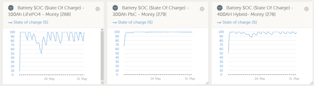
I have on the graphs below shown that period as the first few hours of a full 2 week period where the battery bank is in fairly light use (no more than 50Ah drawn) and being recharged primarily by solar. You see that the Lead is not really in use once this initial recharge is finished and all the power for this fortnight is being provided by the Lithium – which also means the Battery Bank is getting very efficiently recharged by the solar.
The Chargers I have in my setup I can limit the duration of the Absorption Phase (the charging phase where the voltage will be at 14.x V. This phase is also called the CV – Continuous Voltage – phase for that reason) so Lithium Battery will be less impacted, but it is still a consideration.
On a charger without that level of control it could be a concern for optimization of the setup. Clark (of Emily & Clarks Adventure) has developed a charger that will manage this and depending on your setup it might well be worth discussing this device with him. I’ll probably also try Clarks charger as well as it sounds an exciting product.
Basically, this Post-charge Absorption/CV phase is in my opinion the only real potential issue with the Hybrid Battery Bank. The data analysis I was able to do and showed earlier meant I could get a good insight into how to manage this.
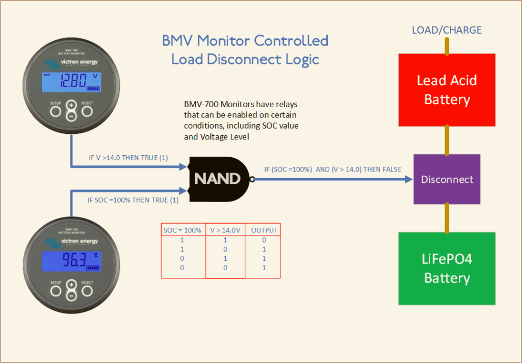
On my own setup I will know when the LiFePO4 Battery is full as the Victron BMV monitor on that battery will report an SOC of 100%. I will know when there is a charger on and actively charging as the voltage will be around 14V or more (as long as it is above float is the key). If the charger can provide enough power for any loads as well as putting some charge in, the voltage stays high, therefore I will also know when there is a net load on the system as the voltage will be below the float voltage.
This means I can apply some simple logic rules:
- IF SOC = 100% AND V >14.0V THEN Disconnect Lithium. So this means battery is full and there is no system load that requires any battery power.
- IF V < 13.5V THEN Reconnect Lithium. This means as soon as all chargers are switched off, the Lithium will rejoin the Battery Bank. It will also rejoin if there is a load that cannot be met by the charger as that would result in the voltage dropping below the float
(note that the voltage numbers above are just illustrative to explain the logic).
With the Victron Monitors I have installed, I can use the logic above for the following conceptual setup
There is a body of opinion, of which I am inclined to agree with, that says you get a longer service life out of a Lithium Battery if you don’t actually fully charge it. You lose some ultimate capacity but you gain with a longer life.
So on that basis you could actually just use a voltage-level disconnect logic and forget the SOC check. Or set the SOC value to 90% or 95% for the ultimate fine-tuning.
As it stands, it is not actually a show-stopper in any way, but having a device in place to address would be an useful enhancement to an already practical setup.
Monitor Independant Charge Disconnect Device
Fixing this “float issue” can be addressed in a number of ways and you don’t need to have BMV Monitors installed to have a solution for this.
For this reason I have developed a special Microprocessor-based Control Device that is not dependant on, and will work independently from, any Monitors, but can still apply the above Voltage Logic to automatically disconnect the LiFePO4 Battery. This device is a latching unit which means very minimal current consumption in either on or off state.
The VSDR-200 Lithium Controller is shipping and we have sent these throughout Europe, in the USA and to Australia.
Also see this page to read more about the VSDR – (TBA)
A future version of the VSDR-200 will have the ability to incorporate the Battery SOC check logic for enhanced control should the user have a BMV-700, BMV-702 or BMV-712 Monitor on their LiFePO4 bank and wants even greater flexibility.
Ready to see the Conclusions?