I bought a 12 year old Autotrail Cheyenne Motorhome in 2020. It was in great condition, but the electrics would have been regarded as a little dated even in 2008. The following series of posts discussed the various upgrades carried out. Some of the changes mentioned I later changed further in fact, so this is pretty much a Journel of Adaption
Part Three. Original Electrics cohabiting with new Electrics
As mentioned, I want to use the original electrical setup where appropriate and use the new components in conjunction.
Split-Charge
The Cheyenne has a multistage powersupply in the EC325/328 PDU – this works on both AC Mains and DC Alternator. Quite a clever idea it has to be said – but the downside is the very limited output, which sadly makes it of very little use for either purpose.
The function of the built-in 10A DC-DC Charger is therefore being replaced by the Ablemail AMC 12-12-60 60A Battery to Battery Charger.
What was needed in order to make sure the new B2B was not confused by another charger running in parallel was to disable the built-in unit. There are a few potential paths, but which is suitable depends on how the Sargent kit has been wired up by Autotrail.
The Motorhome has as part of the installation an auxilary control unit from Sargent – an EM50 Intelligent Interface Adapter – used for various functions. One of those is potentially for the Split Charge (see picture below)

As can be seen, Fuse #8 is meant to protect the Split Charge Supply. So removing Fuse F8 disables the Split Charge? Um, no. It makes no difference (but I guess the ** does say ‘Depends on vehicle specification’)
What I needed to do with the Cheyenne was to use an alternative control input instead. There is an ‘Engine running signal’ on a connector block coming into the Sargent PDU (pin #9), as noted in the diagram below
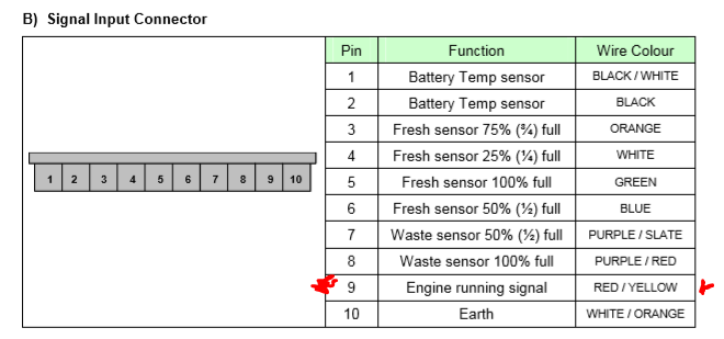
Disconnecting this signal stops the integrated Split charge working – so that fixes that problem.
However, there is more then that function that happens when the engine starts – so what about those? It is important to know the full consequences…
Other key functions are:
- The 12V supply to the Fridge that activates when the engine runs;
- The door step automatically retracts; and
- The Habitation Electrics get turned off.
#1 is a key function. Fortunately the way the Sargent is wired as standard there is a relay outside of the PDU that activates when the Engine Starts (activated by the D+ signal) and the output of that relay goes to both the Fridge AND the Engine running signal to the PDU. So removing the input to the PDU has no impact on the Fridge 12V Operation.
#2 is very important as well. It is possible to press a button to retract the step but for safety reasons, an automatic retract is very desirable. This function is managed by the EM50 and I have made no changes to that, so this continues to work as before.
#3 is an interesting one. Having the habitation electrics disconnect when the engine starts is not always a great idea. They also don’t reconnect by themselves when the engine goes off. By disconnecting the Engine running signal into the PDU, this auto-disconnect no longer occurs. Generally, I regard this as a plus actually, as it allows me to chose to leave them on, or to disconnect using the button that Sargent provide on the Control panel.
[I have found I need to remember to ensure the water pump switch is OFF however, as the water movement in the tank when driving will cause the water low alarm to go off]
Mains Charging.
The Sargent PDU allows you to charge either the Starter Battery or the Leisure Battery by selecting which battery is being used on the control panel and turning the Charger switch to on. Doing this will activate a 10A charge.
The new setup with the EasyPlus gives a 70A charger, but this will only operate on the Leisure Battery.
It is easy however for me to charge the Starter Battery still. When on EHU, I can still select the Starter Battery from the Control panel and turn on the Sargent Charger. This will result in having the 10A integrated charger working on the Starter Battery and the 70A EasyPlus charger working on the Leisure Battery.
If I don’t switch to the Starter Battery, I will just leave the Integrated Charger off, and the Ablemail AMT12-2 Battery Maintainer will put a pulse charge into the Starter Battery. Generally this method will be sufficient to keep the Starter Battery at around 12.8V unless there is a reason why I need to do a ‘proper’ charge into the Starter Battery. I think it is a good idea to periodically do a full charge on the Starter Battery for extending the service life of these, so I would probably set the switches to do the EHU Starter Battery charging process once a month or so.
Solar Charging
There is no Solar setup installed, so nothing to integrate with the existing setup. The Sargent unit does have a Solar Controller built in probably (I say “probably” as they did originally, but I understand they get removed sometimes when serviced or upgraded), but they are limited to just 120W I would not be using that anyway even if present.
The Victron MPPT will take care of this and similar to the Mains Charging, the Starter Battery will get a pulse trickle charge via the AMT12-2 while the Leisure Battery gets its normal charging from the PV Solar Panels.
That pretty well covers the co-existance with the 12V Side of the Electrics. Next will be the 240V side….
240V Electrics
The Factory Sargent EC325/328 includes a Consumer Unit with incoming RCD and 3 MCBs – one general use, one dedicated for the Truma Ultraheat Heater and one for the AC Lights, Battery Charger, Water Heater and Fridge.
I am using the CU features of the EasyPlus to add flexibility to the existing AC setup. Some of this will be in the future so is in my ultimate plan but cables are routed ready to fit, so just half a days work basically.
What is the target?
Want to be able to use the general sockets off the inverter whenever I want to – so stuff like Laptop Chargers, AC Battery Charger, little Induction Hob, Slow Cooker, that kind of thing. Obviously there is a need to make sure there is enough battery capacity for this.
The Truma Ultraheat in Electric mode is not really something I expect to run off the Battery Bank
The Water Heater and Fridge are ones which could be useful to be able to run off the Batteries in the right circumstances as they are either short bursts of higher power (Water Heater) or extended times of lower power (the Fridge). This would work well at times of good Solar Harvesting where for extended periods of the day, all or most of the enegy the fridge wants could come from the PV Panels.
How to achieve this in a simple way? or at least, in a simple way to use if not to initially setup anyway. Note. When I say “simple way”, I am really meaning a simple way to use, which may involve some initial complications of course!
Here we go …

[SPOILER ALERT: Changes were made to this area as time went on. Items like the original 3-Way Fridge was replaced and I changed around which MCBs were used for which purpose but I am leaving this section showing the initial installation as it is all part of the ‘journey’ I went on modifying and updating the Motorhome]
To the EasyPlus, I ran a fresh cable from the Hookup External Plug to the AC In
Coming out of the EasyPlus, there is an RCD going to four separate breakers (MBC 0 to MCB 3)
MCB 1 was cabled to connect to the original Cable that goes to the Sargent PDU. As it stands, that is how things are running and the remainder will be changes and updates.
This breaker is driven by EHU OR Inverter
MCB 3 is a brand new addition to the electrics. This will go to a dedicated externally accessible socket. I have a socket like this on my Campervan and while I don’t use it a lot, when I need it, it is really handy to have. LIke MCB 1, this is EHU or Inverter driven.
MCB 0 and MCB 2 are the interesting ones.
MCB 0 is an output that is only live when there is an live input into the EasyPlus. Unplug the EHU power and MCB 0 goes dead. This makes this ideal as a source for the Ultraheat Room Heater as there will be no risk of draining the batteries if the power is lost. I will in the future be connecting the cable that goes from MCB 0 to the cable that goes to the Room Heater.
MCB 2 is an output like MCB 1 – It is live on Hookup or Inverter.
What I have done is use an auto switching relay that has two sets of inputs – one from MCB 0 (so mains only) and one from MCB 2. The delay is by default on MCB 2, but if it detects power on MCB 0 (so live AC in), it will switch to that. This means it will always use direct mains when available, but when not, will use the MCB 2 source.
The output of this auto switching relay will then (once cabled up) go to both the Fridge and the Water Heater
The next step to this is to have an AC SSR (Solid State Relay) between MCB 2 and the auto switching relay. This allows the MCB 2 input to be disconnected via a 12V DC control line, so if I want to, I can remotely disconnect MCB 2 if say I think the Battery Capacity remaining is getting a bit low.
What I can now do is connect that control line to a programable relay on the Victron Cerbo GX. This relay can be configured to go active/inactive depending on a variety of parameters. I am using the SoC (State of Charge) parameter to have the relay active once the State of Charge hits a chosen value. This way, you can automate how the Fridge and/or Water Heater will come on and off depending on what battery capacity you want to keep in reserve.
Fort example, in the summer, you might find the solar is very effective and you can afford to have the battery drop a bit as you know you will make it up the next day. And in winter, you know you will have more lights on for longer, and the heater fan on, plus solar won’t be recharging the batteries, so you adjust the SoC value so you disconnect at a higher level.
This automated and intelligent use of available battery power, driving appliances like an AES equipped fridge which will use the AC input, and if that drops, switch to gas, will give the best use of the cheapest available power in a seamless manner.
This is the plan anyway!
This is what the Auto Switching Relay and SSR with its cabling looks like in ‘real life’

I’ll be tieing up the cable connections to Heaters and Fridge in the next part of this series.