I bought a 12 year old Autotrail Cheyenne Motorhome in 2020. It was in great condition, but the electrics would have been regarded as a little dated even in 2008. The following series of posts discussed the various upgrades carried out. Some of the changes mentioned I later changed further in fact, so this is pretty much a Journel of Adaption
Part Two. Installing the Kit
Breaking this into logical chunks now …
Batteries
The Autotrail Cheyenne has a good sized external battery locker that currently contains a pair of 100Ah AGM Batteries. I was thinking of using that to fit a pair of new batteries (initially Lithium being the plan, but changed to Lead-Carbon) in the same place, but after playing around with ideas and options, using battery mockups made from Cardboard (a lot lighter to move around), I decided to install inside the living space.
The weight aspect was a consideration – 60kg hanging on a strap is a fair weight and I tend to be fairly cautious when it comes to fixtures and fittings); Cable lengths and routing internally would be a lot shorter and tidier; I could use the external locker for other things that I maybe would not want to carry inside (my frontier stove is a good example); and also, going inside would allow me to have an extra battery if I wanted.
This is one of the batteries. What I found slightly unusual on these compared to other lead batteries I have installed – and a distinct advantage – is that the top is flat. This means you have have a cable going from battery to battery in a straight line rather then having to route it and twist it around a raised section by the terminals.

Not got a photo of the batteries just in position to show them, so this is with the inevitable cable nest on top

So three batteries in parallel, with short interconnect cables. I am mosting using cables I had knocking around for this in fact. For this setup I would use 25mm2 cable minimum as interconnects, but am in fact using 50mm2 as that is what I had handy – so pretty chunky! The battery bank is protected by a MegaFuse (the black block on top of the middle battery with a 225A Fuse fitted) and then goes to a switch to allow the bank to be disconnected from the system.
Inverter/Charger
[SPOILER ALERT: I later relocated the EasyPlus and other Victron devices into a repurposed External Locker. I am leaving this section showing the initial installation as it is all part of the ‘journey’ I went on modifying and updating the Motorhome]
EasyPlus Charger/Inverter. The Victron EasyPlus is fitted on its back between the battery bank and the front of the storage section

Three categories of cabling goes into the bottom of the EasyPlus …
1) 240V AC Cables – these are the Orange, Blue and Yellow mains Flex. The typical Multiplus has just one or two AC cables out, depending on which model it is. But with this EasyPlus, there is one incoming AC Cable in and actually FOUR AC Cables out! I’ll cover this more later on why there are 4 and how they will be used.
2) 12V DC Cables – There are a pair of 35mm2 DC Cables (one Red + one Black). The +ve Red goes to the Master Switch mentioned on the battery section & the -ve Black goes to the BMV Shunt.
3) Control/Data Cables – There is a Temp Sensor pre-fitted and a cable from the internal connection goes to the sensor (interestingly, I am NOT going to use that sensor as cabled) There is an RJ45 Cable fitted, connected to the VE.Bus port inside the Unit – this will go to the Cerbo; And the final cable is the white cable coming out and currently I don’t have a use for. This is wired to an internal relay in the EasyPlus and I wired up the cable as if I do find a use for it, it will be a lot easier to connect it up that way.
The other remaining devices will be mounted on top of the EasyPlus, but in order to be able to secure those device and also have the EasyPlus servicable and keep enough airspace around for ventilation.
In order to do this, I just made up a removeable platform from Ply (the vertical side will actually go between the EasyPlus and the Batteries)

This slides into place, supported by modesty blocks attached to the storage area sides and then screwed down to stop it moving.
Other Devices
Covering the B2B, MPPT, Cable Protection and Monitoring now …
Secured to the Platform above are the various devices mentioned
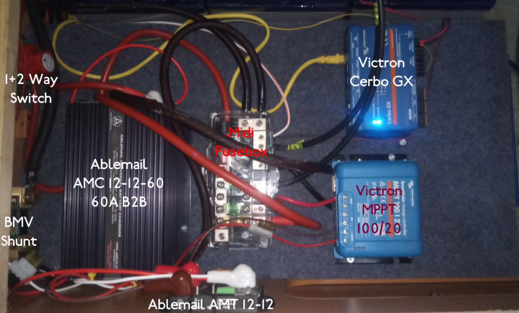
Listing the devices shown above:
- BMV Shunt: This is for the BMV-712 Monitor. Got the Easyplus -ve Cable and a fusebox -ve going to the LOAD side of the Shunt, with the BATTERY side having a single connectiom, that being the battery bank.
- 1+2 Way Switch: I used this switch to allow me to be able to isolate the Battery Bank AND isolate the EasyPlus (switch Position OFF); disconnect the EasyPlus from the Battery Bank & Hab System (switch Position 2), or to disconnect the Hab System from the Battery Bank, but keep the EasyPlus connected to the Battery (switch Position 1); OR – and this is the the default operational setup – have everything in play (switch Position 1+2).
This just adds useful potential flexibility for servicing needs. - Midi Fusebox: Using this to distribute DC power in a protected centralised way with suitable fuse protection (I flinch when I see these installations which have a big stack of cables on top of the battery +ve terminal). This box gives a nicely managable setup in a neat way (my cabling may go over the box but it is well secured and easy to work round)
- Victron SmartSolar MPPT 100/20: The Solar Controller is in place and wired up apart from the PV cables. These are routed but will be connected when the PV panels themselves are ready to be fitted. I am using the Load Terminals on the 100/20 currently to run to a
- Ablemail AMT 12-12 Intelligent Battery Maintainer: This keeps the Starter Battery maintained using a pulse charge of 3A every 20 seconds of so. There is no specific need to use the Solar Controllers Load Terminal.
I have the MPPTs LOAD connection set to be always on, so this means that it does not only work when there is solar but works as a direct passthrough connection and is just a convenient way to connect as well as allowing me (geek alert) to use the SmartSolar to monitoring the LOAD current and see how the AMT is working. - Ablemail AMC 12-12-60 B2B Charger: The Ablemail AMC 12-12-60 is a Multistage Battery to Battery Charger with an output of 60Amps at whatever output voltage is configured. This specific model is setup for a 12V Starter,12V Habitation configuration
The B2B was maybe the most awkward of the devices as needed to get a cable from the Starter Battery to the B2B (could not rely on any existing cable as the factory installed setup ran at significantly lower currents and Motorhome manufacturers are not reknowned for using oversized cables!).
The photo below shows the Starter Battery +ve Terminal Block. All the standard fused lines are in use, so I picked up the corner one and added an in-line Fuse holder (with 80A Fuse) a few cms after the battery connection.

- Victron Cerbo GX: This is the Heart of the system monitoring and there are cables from the EasyPlus (VE.Bus), BMV-712 and MPPT (VE.Direct) into it, plus a couple of Relay outputs and a couple of Temp Sensor connections (more on these later), plus a GPS Dongle.
Cable Routing
So that covers all the devices installed in this storage area. There are lots of cables needed to be routed here and trying to do that neatly was certainly a challenge! The Autotrail routing of cabling used a void the went from the corner top locker down to under the van and then routed in various directions. I looked at utilizing this route but ultimately discounted it as virtually impossible to access and went a different way
Decided to use the void within the Cab B Pillar instead. Autotrail puts a trim piece over the pillars, so it was a matter of removing the trim, running the cables within the void (making a hole in the side of the storage area that would be hidden by the trim) and then replacing the trim.
I don’t have a ‘work-in-progress’ photo for the cabling, but this is the B-Pillar after the cables are routed and the trim replaced

You can just see a hole with a black and red cable poking out – that is the cabling from the Starter Battery. I was actually going to make a cover to follow the line of the bottom dark grey moulding to cover this , but the original trim adapted so closely I’m sure if I will bother as that part is hardly visible anyway?
And finally, back to the Storage Area and what does it look like now? Well everything is inside one side of the Storage area and I can lift up one cushion to see inside and access the Isolation Switch, as well as accessing the EasyPlus controls and Breakers by dropping down the front hinged flap.

So that completes the Physical Installation. The next post will be how it actually works together and how I am dealing with system duplication i.e. AbleMail B2B and Sargent Split-Charge, and EasyPlus Mains Charger and Sargent Mains.