I bought a 12 year old Autotrail Cheyenne Motorhome in 2020. It was in great condition, but the electrics would have been regarded as a little dated even in 2008. The following series of posts discussed the various upgrades carried out. Some of the changes mentioned I later changed further in fact, so this is pretty much a Journel of Adaption
Part Five. Additional Automation and Control for Fridge and Water Heater
Additional Controls
Need to use an extra bit of kit and rejig the 12V signal wire to the SSR a bit, but should work out well I think.
Revised setup in the picture below:

The NC output of the Cerbo used to go to the +ve of the SSR but now goes to the NC of a Countdown Delay Timer Relay (lets call this the CTR)
The COM of the Countdown Timer Relay now goes to the +ve of the SSR.
This means if the Countdown Timer is not running, the SSR will be either On or Off depending on the state of the Cerbo Relay – so just as described earlier.
But while the Countdown Timer IS running, the CTR will be enabled, and instead of NC and COM connected, NO and COM will be connected. This means COM will carry a +12V level and the SSR will switch on, so regardless of the Cerbo Relay status, Power will be available on the Fridge/Boiler circuit from the Inverter (assuming EHU not live. If EHU is live, all this is irrelevent! This is about off-grid operation only).
To activate the Countdown Timer, a momentary push-to-make switch makes a connection to two pins and starts the Countdown. If the Switch is pushed again whilst the Countdown is running, the timer is disconnected and the CTR is switched off (and the SSR is controlled by the Cerbo again).
The timer I will be using is this one – https://amzn.to/3hrtILx

There are quite a few around, but most have a very limited delay duration of just a few seconds, with the odd one maging 999 Seconds (16 Minutes) and I wanted a longer countdown. The one above is the only one I could find that can be set to a decent duration – upto 99 seconds or upto 99 Minutes. A 60 or 90 minute (1 or 1.5 Hr) override will work out fine I think
I could have gone for the Chinese stock rather than Prime stock and saved about half the price but too impatient to wait a month! This should arrive tomorrow
Last unanswered question …. How much power does this use? Well, when it is running, the overhead of the timer will be noise compared to the AC power being used, but when not running and in standby, it could add up! In the text on the Amazon listing it says “… normally the module will start to work when triggered, if you need module to work immediately after power on, connect 2 terminals of trigger”.
Now exactly how to do what it says is unclear, but I think it means you can wire it up so it only uses power when it is doing the countdown so when not in use, zero current overhead.

OK, got the countdown timer module today and tried it out on the bench …
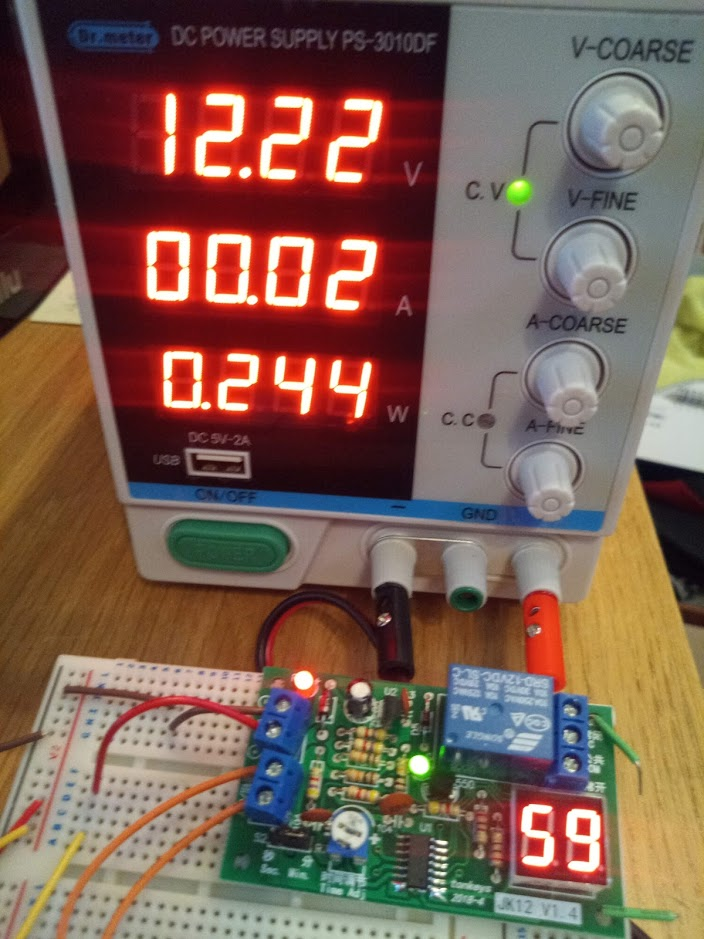
Looks decent enough and seems to work well (on a timed test, 1 minute on the timer is 1 minute in real life down to as close as I can tell). The current draw seems to be pretty low. When the timer is counting down and the relay is on (the little green LED on in the middle of the board), the device draws between 10mA and 20mA (the granularity of the display means it alternates between 00.01 and 00.02).
When the countdown timer is reset, there is no current draw shown by the PSU. Obviously there must be as the LED display is still lit, so I am guessing it must be under 0.005A (5mA). 0.005A on a 12V system works out to be just under 1.5Ah/Day.
When a camper/motorhome is in use, 1.5Ah a day is not a great deal, but can add up of course on a system that is parked up in storage, so this would be device you might well switch off. (As a comparision, the BMV-712 with no backlight consumes 1mA).
Now the comment “… normally the module will start to work when triggered, if you need module to work immediately after power on, connect 2 terminals of trigger” would point to a way to fix power use in standby and I think I have worked out what the above means.
By connecting the 2 trigger pins together permanently and connecting a switch to supply power, as soon the switch is turned on, that provides power to the unit, the countdown starts and then when the time is reached, it goes into ‘standby (still with power active) and to restart the countdown you turn the switch off and back on.
That is maybe the best way to wire it up to avoid any power use when not needed?
Ready to install a LEGO box in the Motorhome now

Or more precisely, the Countdown Timer in a Lego Box …
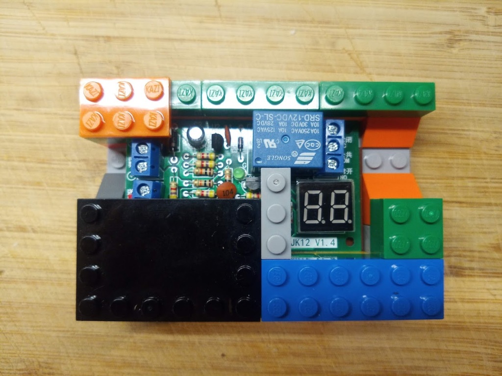
I find using LEGO type bricks to make enclosures very handy. This unit will generate a tiny amount of heat (1/4 Watt for an hour at a time) so the holes for the cables will be plenty of ventilation.
Installing the Countdown Timer
Made a extra alteration to the design which adds an extra level of flexibility to the operation
Within the dotted line in the schematic below is the Timer and Switch I am just installing.

The operation works as follows:
Delay Activate Switch is now a 3-way On/Off/On switch.
- In position 0 (Off – as shown above), the Timer (CDT) is off, which means the CTD Relay connects NC (from Cerbo) to COM (to SSR). This means the CDT is bypassed and the SSR state is solely determined by the state of the Cerbo Relay.
- In position 1 (On, switch to the left), the CDT gets power and starts its downdown. This enables the CTD Relay, which connects NO (which has a +VE signal) to COM, thus turning on the SSR. As soon as the Countdown hits zero, the CTD Relay turns off, and again the SSR is controlled by the Cerbo only.
I have set the countdown duration to 60 minutes – so as soon as the Switch is in position 1, the SSR will be force-enabled for 60 minutes and then revert to Cerbo Control. To get another 60 minutes of timer, the Switch needs to be put back to position 0 and then position 1 again.
To cancel the timer early, simply put the switch back to position 0 and leave there. - In position 2 (On, switch to the right), the CDT does not get any power and so no timer is active. However the CDT Relay COM is connected to +VE directly and as the COM is routed to the SSR, the SSR will be on all the time the switch is in position 2 and the Fridge and Boiler have AC Power available.
So in summary, with this switch I can (in P2) force the Fridge & Boiler circuits to work like the other circuits in the Motorhomer i.e. On EHU or Inverter regardless of any Battery level; or (in P1) work for just 60 minutes regardless of Battery level; or (in P0) be controlled fully dependant on Battery level.
In terms of switch location, I fitted it in a double-CBE mount behind the Drivers Seat.
So normal MO, the switch is in 0/Central – and I just flick it to 1/Up to have a 60 minute override. I don’t really expect to use 2/Down but it’s there if need be.

Decided to fit a double mount as I tend to sit on the bench on this side and thought it would be handy to have an AC socket here for the laptop charger (there is an AC socket as standard in the similar location behind the Passenger Seat.
As an aside … that white stuff in the bottom right corner? Bit of a design faux pas by Autotrail. When the Drivers seat is swivelled, once it is turned past a certain position the release lever hits the side and scrapes the veneer. So these are scars earned over the last 10 or so years. I think they should have really had some kind of mechanical stop to prevent it turning too far.
EasyPlus AES (Automatic Energy Saving) Control
Earlier I discussed the instalaltion of the EasyPlus which lets me use off-grid 240V (via Inverter) on just about every circuit except the Room Heater.
I added the WAS-201 Auto-selecting AC switch to allow additional control over the Boiler and Fridge circuits to avoid draining the battery too much.
Adding in the Countdown Timer increases the flexibility of this circuit to allow it to be always available or just for a limited time even when below the chosen battery charge level.
There is one more thing that needed sorting though….
The EasyPlus is configured in AES (Automatic Energy Saving) mode so the inverter is in sleep mode unless called on (and in that mode only uses around 2W). The downside of this is that if you want to use the inverter for a small load, it won’t switch on to drive that device.
A resolution for that is installing what are called ‘Assistants’ into the Victron EasyPlus.
Three Assistants are installed – one (general flag) configured to disable the AES feature when active; another (programmable relay) to activate the general flag and a third (programmable relay again), but this time to deactivate the general flag. And the control signal is sent to the Temp Sense [as that is the one and only control sensor on the EasyPlus/Multiplus 1600 – Larger Multipluses have a couple of inputs for this kind of thing].
It does not matter that I no longer have a Temp Sensor on the EasyPlus as I am monitoring the Battery Temp via another device (I am using the Cerbo which has 4 temp sensor inputs, but other Victron GX units or a BMV could be used).

To control this Assistant, you can use an external mechanical switch or, as I am doing, a remote relay. I am using Relay 2 on the Cerbo to run the assistant and so to force the Inverter to be active when off-grid, I go into the Cerbo Control Panel and turn the relay on.
I might use a switch instead to make it easier. I could even install another Countdown Timer in the same manner as I am doing the Boiler/Fridge setup to ensure I don’t forget to re-enable the AES.
[SPOILER ALERT: This control had some later refinements after I changed the Fridge . I am leaving this section showing the initial installation as it is all part of the ‘journey’ I went on modifying and updating the Motorhome]
Leave a Reply