I wanted on-tap hot water in Clarence, my Campervan Conversion, but I don’t have – or want – on-board plumbed in Gas, and I didn’t want to fit an expensive Eberspacher water heater, so took a similar approach to this that I have done with other aspects of the build.
That is to repurpose domestic products for Campervan/Motorhome/RV use, just like I have done with the 240V Fridge and the 240V Induction Hob.
Part One: The basic heater and kit and the plumbing side.
The Heater is an oversink semi-on-demand Water Heater by Ariston. It has a 2kW Heater Element and a 10L Water Tank in an insulated housing. This is the installation in my underbed ‘garage’ in Clarence.

This is a Pressurised & Unvented Heater, so alongside the actual Heater itself, I fitted a Pressure Release valve that automatically opens at 6BAR (the heater is rated to run between 1 – 3.5 BAR). These pressures will be virtually impossible to actually reach in a camper, but the valve also acts as a drain tap so is still handy to have.
Along with the pressure release valve I have a small expansion vessel of just 2L. Again, similar to the PRV, The heater is unlikely to get to a pressure where an expansion vessel is a requirement, but as well as working as a ‘safety net’ it also provides a way to feed a small amount of water through the tap without the pump running, which is handy at nighttime, as the pumps can be rather noisy.
Talking about pumps, the entire hot and cold water system is fed via a pair of 25L water tanks with a Shurflo on-demand pump to send the water through.
The final bit of the underbed system is the stop-valve that can isolate the hot water heater plus peripherals from the basic cold-water supply.
Both hot and cold supplies then go via 12mm JG flexipipe to the Hot+Cold Mixer Tap in the Galley Kitchen. I will be also teeing off on these suppliers to feed an external shower connection.
Part Two: The Electrics
At the time I installed the kit, I had an EDECOA 2500W (5000W Peak) PSW Inverter; connected to a Battery Bank compromising 4 x 95Ah (C20) 12V AGM Deep Cycle Batteries, gving a total of 380Ah. I later changed the setup to a Victron Multiplus 2400W and 645Ah of AGM Lead Carbon Batteries, but the Water Heater worked great on both setups and needed no alterations.
Note that all the data below was from the original electrical setup.
My Test Routine was to set the Heater at “E” for Eco Mode (this doesn’t change the power setting, it just sets the thermostat lower so the heater will turn off sooner);
Check the water temp at start (running tap to remove any pre-heated stored water) & check water at end to ensure the heater has operated as required;
Remove any intermittant or high loads to avoid skewing data (so Victron Inverter off and only real loads were lights in garage and power to Raspberry Pi running Venus GX)
Then turn the Inverter on, then the remote switch on and leave until the heater has hit the set temperature;
Finally check the data recorded by the Victron Venus GX software via the VRM Portal (I sample the battery voltage, current draw and battery SOC on a 1 minute cycle)
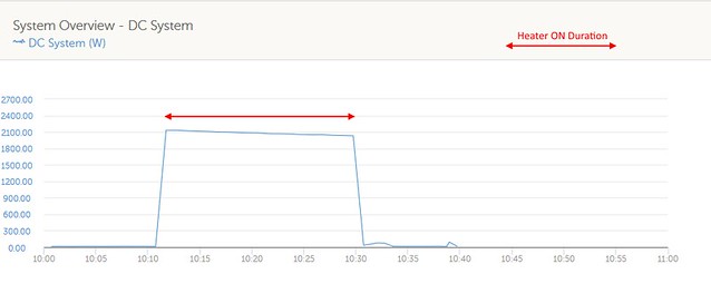
Run 1. Use as Supplied
The Battery was at 85% SOC when the run started
Heater ran for around 30 minutes, drawing around 2100W – so around 1kWh of power
There is a significant voltage drop, dropping to 11.7V initially and by the end of the test, the battery voltage had dropped to below 11.5V
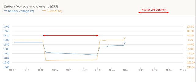
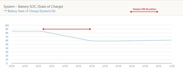
By the time the heater had finished, the SOC had gone from 85% to just under 60% – so a drop of 25% using 1kWh of Power, which is pretty well as expected for the size of battery bank and the C-rating of the current draw
A constant 180A current draw for nearly 30 minutes is a big ask on a battery bank. I monitored the cable run temperatures and the cabling got pretty warm, and there was an isolated hotspot that reached >100 Celcius around the 300A ‘catastrophic’ fuse holder.
One aspect I was impressed with was the Inverter. Inverters outside of the top brand names are very often capable of much less then their marketing suggests. On this test, the EDECOA Inverter casing (which works as a heatsink) only touched 30C in very isolated spots and the cooling fan only came on around 15 minutes into the run. There is also a voltage drop (checked with meter) of 0.44V between battery and inverter terminals, which means the inverter was operating without problems at just above 11V.
Run 2. Cycle power on and off 50/50
The Battery was recharged back to 85% SOC when the run started (I didn’t leave time for the voltage to settle after charging so voltage appears higher)
This time the Heater was set to run for 60 seconds, then power removed for 60 seconds, then power restored. This loop was continuous and left running until the heater turned itself off.
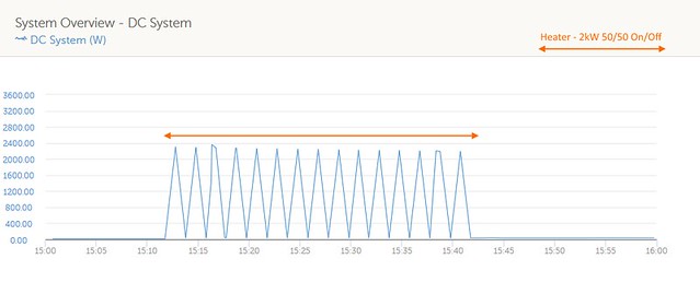
This graph shows how the power is cycling on and off;
The run time is just over 40 minutes this time. One reason why it is not longer (you might expect twice as long to run with the power interupted half the time) is the water start temp was 7C higher (11C instead of 4C) as the test was carried out in the afternoon when the ambient temp was higher.
The voltage drop on Run 2 is noticebly less

I believe allowing the batteries to have a 50% recovery time during the Run helped reduce this, and this will be better for the bank
And the SOC went from 85% to around 63%. Not as low because the Heater started off with a warmer volume of water, but the longer time is definately more battery friendly.
This Graph is interesting as it shows side by side the two different approachs and how the Voltage and Current looks for each (of particular interest is the blue – voltage – line)

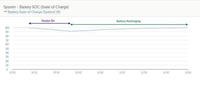
Run 3. Cycle power on and off 30/60 whilst Charger on
The results of Run 2 made me think I can improve further on a Campervan-friendly configuration.
For this next run (#3), I set up the control to have the heater on for 60 seconds, off for 120 seconds, then back on for for 60 seconds, etc on a constant loop, with the heater eventually turning itself off when water upto temperature.
This will give an average power of 700W on the overall cycle; the Time taken to heat the water will be 3 times longer but speed of water heating is not a priority. What I also did in Run 3 was plug into the Grid so the battery charger (35A capable) will be replenishing power. Not at the rate the heater is using it but if the heater runs for an hour, that power could be put back in 2-3 hours potentially. See the chart below which illustrates this for Run 3.
I should make it clear that the Heater is powered by the Inverter regardless of any hookup. This is deliberate as if plugged into a current-limited EHU, the water heater coming on could overload the external feed if I am using other AC loads. (when hooked up, all other devices plugged into both the EDECOA and the Victron Inverters will be switched automatically to external AC power).
This is the power use pattern
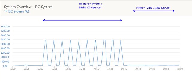
Run time is around 35 minutes (I think the ambient water temp was again higher), and what is intriging is the power hits 2400W each time. TBH I am not fully sure why, but if that was extra power used by the heater it would explain the quicker then expected heater cycle run.
The most important graph is the Voltage and Current one though.
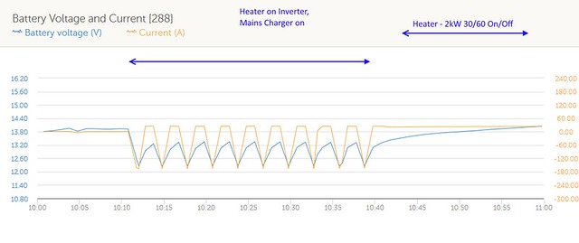
Now this time, we started from a fully charged battery bank, but at no time did we drop below 12.2V and the current draw was around 20A less due to the charger providing direct help.
Clearly the EHU helped here, but is this an ok test if I am claiming this is useable as an off-grid solution?
Well, actually yes it is.
I have a 35A Smart Charger – this puts in a maximum of ~400W into the battery.
I also have 400W of Solar Panels. So while I wouldn’t expect 400W most of the time, in the summer they will provide a very useful recharge (and in the summer I am usually fully recharged by lunchtime, so the afternoon charge could effectively feed the Water Heater)
And driving I have a 40A B2B – so again, very similar to the Mains Charger (I also have a 100A VSR which I have tested at 80A output when the load demands it so can switch to that if the heater is on and the batteries are at a lower SOC)
Lithium Batteries for this application would be perfect of course as there would be no voltage drops, but the Inverter seems to cope fine at the voltages tested at and the batteries in the bank are spec’ed to allow a higher than C/4 discharge so that aspect is ok as well.
Third and Final Part – Controlling the Heater
The Water Heater is a 2kW System and has no power control available – But I want to control it. Hmmm.
An aside but an idea ….Now I have a 2kW Induction Hob also in the Camperbus. Like all hobs, it has different settings – There are 8 power settings available between 200W and 2000W and I tend to use the 800W setting for something like boiling a kettle as I find it both plenty fast enough AND it is kinder to the battery bank.
For anyone who has used an Induction Hob, they have probably noticed that if they are doing something like simmering soup or veg, the liquid will bubble every second or two? This is because the Induction Hob does not really run at a lower power at the lower settings, but switches between high power and off at a frequency that gives the selected power as an average. And it is this method of working which made me think the same approach could work on a 2kW Water Heater.
1) Remote Control of the Water Heater
The Heater, the Inverter that drives it and the sockets and plugs are all located in the Garage below the permanent bed. So I didn’t want to have to crawl under the bed to turn the Water Heater on every time.
So I have a switch in the kitchen to allow me to remotely control this.
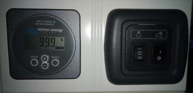
The BMV-712 Monitor is on the left; The switch set on the right has the Water Pump on/off switch on the right, and the Water Heater switch on the left. The Heater is a two way switch – Position II turns the heater on; Position 0 is the off one of course; and position I is a BMV controlled position.
I can set the BMV Relay to turn on and off on various selected parameters. I have it set for the relay to turn on and off depending on the SOC (State of Charge) values. The relay is also controllable remotely via the Victron Bluetooth App.
Of course, this does also rely on the Inverter being on. I use the high power Inverter as an “On Demand” Inverter so tend to only switch it on when using selected devices (the Fridge and Internet Router/Radio work off a different always-on Inverter), so if I wanted the Water Heater to come on automatically at the set SOC level, I’d have to remember to leave the Inverter on as well (luckily that also has a Remote Control On/Off as well)
The output of the BMV Relay is a DC signal, so I fitted an SSR (Solid State Relay), in line with the power from Inverter to Heater, which allows a DC level signal control over an AC Circuit.
2) Power Control of the Water Heater
As I said, the Water Heater has no Power Control, but I want to run at a lower power than 2kW. So I decide to copy the way the Induction Hob works (as would have been seen if you read Part 2). But How?
Actually, very easily. I just installed a DC On-Off timer between the SSR DC side and the Remote Control Switch. After a few experiments, I have decided on a 1 minute on; 2 minute off cycle to give a calculated ~700W average power output (1 Minute at 2000W, 2 Minutes at 0W).
* As this is still in the experimental stage, I expect to try different times on the timer for on and off durations, as well as different SOC Relay on and off settings
And this is what the Control Box looks like

The Board with the Display is the DC On/Off Timer (currently counting up to 60 seconds before it turns the output off for 120 seconds).
The White Block just below that is the SSR, on which is fitted a large heatsink to disipate the heat.
In terms of longevity, the On-Off Timer is designed to just run all the time (I will actually be running it pretty infrequently); and the SSR has a typical MTBF in excess of 200 Years when in regular use (far far higher than a EMR).
Now the Heater will be turning on and off around 30 times on each run. I don’t yet know how this will react to this in the long term, but it is a pretty dumb heater with no electronics anywhere, just a heater element, so I think it will be fine, just like a kettle. And similar to a kettle, I am expecting the element to fail through furring up before it would fail electrically.
Please note: If anyone is interested in this kind of project, take the above notes as a disclaimer. I am not making any claims or suggestions anyone should do this themseleves unless they want to experiment.