I bought a 12 year old Autotrail Cheyenne Motorhome in 2020. It was in great condition, but the electrics would have been regarded as a little dated even in 2008. The following series of posts discussed the various upgrades carried out. Some of the changes mentioned I later changed further in fact, so this is pretty much a Journel of Adaption
Part Seven. Relocating the Victron Kit 1.
In Part Two I described the installation of the Victron EasyPlus and other components under the bench seat. I later decided to relocate to both tidy up the electrics and free up space under the seat.
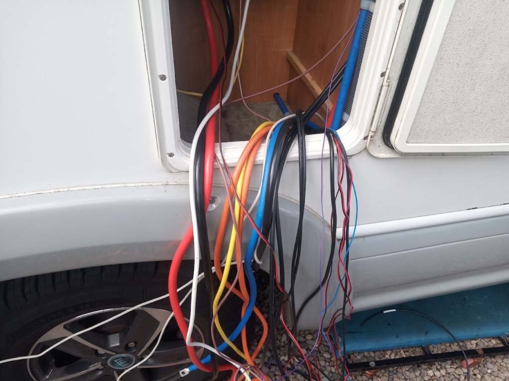
Step 1 – Run & Relocate all the cabling
Step one was to rerun all the cabling in preparation …. It may not look like it, but this is pretty well the “after” shot! There are a few more cables to relocate which will be done in a few days time.
Step two will be to fit the Electrics. – I split this into a follow-up post as this was getting rather long.
New Battery Location and cabling
Battery Bank location adjusted. This is to make room for a Lithium Battery alongside the Lead Carbons (See the series about a Hybrid Battery here). Still using the under-sofa storage but repositioned the Lead Carbons to be both against the front and get some of the weight more in the centre (L-R centre that is).
The Lithium Battery is against the Leads but positioned lengthways. The reason for this is two-fold. It keeps the storage area to the rear a little squarer in space; and it will also let me add a potential second Lithium end on with cabling that would be very straightforward to adapt by just adding a pair of battery interconnects and moving the current -ve cable to the additional battery (cable already sized ready for this).

So the 3 PbC (Lead Carbon) Batteries are set up in parallel in a regular way. The -ve is connected to a dedicated Shunt for a BMV-700.
The LiFePO4 (Lithium) -ve is connected to its own BMV-700 Shunt and the two Shunt LOADs are then connected to a 3rd Shunt which is for a BMV-712.
The +ve’s for the Batteries are setup in a slightly unusual but flexible way.
In the picture above you can see a Green cable coming off the PbC Battery Bank; and a Yellow cable of the LiFePO4 Battery. I decided to colour-code them for easy future identification when I have forgotten what I have done and can refer to the wiring diagram (that I always initially do for future reference but forget to update usually).
The Green and Yellow Cables go to a Isolation Switch that has two inputs and one output.

It is always a good idea to have an isolation switch between the Battery Bank and the Loads & Chargers. In this case, as well as having that switch in situ, using a 4-position switch meant that I could do any of the following:
OFF: disconnect all the Batteries
1: Use the LiFePO4 Battery on its own
2: Use the PbC Battery Bank on its own
1+2: Use both PbC Bank and LiFePO4 Battery as a parallel Hybrid bank. This would be the standard operating mode and also is very simple way to get the two battery types cabled up in parallel.
After the isolation switch, which is useful for maintenance purposes, I have what is referred to as a “catastrophic fuse”. The purpose of this is if there is a serious malfunction of a device or physical damage to a cable resulting in a short or near-short, this fuse will blow and cut off the battery power to prevent further risk.
Size wise, these should be larger than any possible loads you are likely to have and below the amapacity (current capability) of the cabling as you don’t want the cables acting as the fuse.
For info, this is the fuse setup above in more detail …

The Catastrophic Fuse is 225A.
This is fairly low in many ways and if you had say a big 3000W inverter you would exceed that current easily. But this is something where you choose the size based on your own system. My own regular maximum load would be from the inverter in the EasyPlus, which is 1300W, which with inverter overhead means upto 120A draw, plus upto 20A maximum on the Habitation electrics – so I need to accomodate around 150A. Potential surge on the inverter of around 60A from the fridge (lasting around 2 seconds) and so looking at around the 200A area worse case so the 225A I have should never blow in normal service but is lower than the ampacity of the cable – which is 240A constant current.
The Fuse below that is an 80A one and is there for protection on the cabling for the 60A Ablemail B2B. I have an 80A on both the input and output sides.
The final fuses are for the habitation electrics. The +ve is 30A, which is more than can actually be delivered by the source but again is within the current spec of the cable; I have a fuse on the -ve Hab electrics also, of 100A. It is not needed to fuse the -ve cable but I did so simply because it was easier and neater (and cheaper!) to just use another fuse holder rather than find a busbar.
I am relocating all the Victron kit and general 12V stuff to a new place, but I am keeping my Ablemail kit in the front in the gap between Batteries by the batteries for efficiency give the starter battery is of course at the front.

So the AMC 12-12-60 Programmable Battery-to-Battery charger is the main device (connected to the battery bank via 16mm2 cable); Next to the B2B there is an AMT12-2 Battery Maintainer; and finally there is the ABB07 Bluetooth Device that can be used to both program and read various Ablemail units. Here I am using it on the AMC B2B.
Electrics Sled
Now time to work on the other end of “alien resurrection” and finished the Victron ‘sled’ to go into the locker and attach all the cables to…
So this is my new ‘control centre’ – nothing actually really new in terms of devices, just now I have (I think!) finalised my electrics setup, wanted to have a tidier setup for maintenance and servicing.
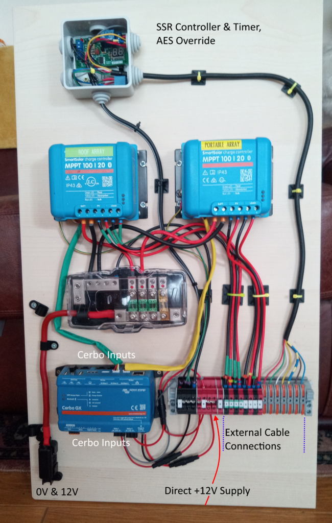
Everything is mounted on a ‘sled’ which can be put into position with just the external connections needed to be made.
The main Battery +12V and 0V are via 16mm2 cable, which is more than adequate for the current loads possible here.
The Cerbo uses a variety of connections – VE.Direct, RJ45, HDMI, USB and Jumper Blocks. For the other various cables I am utilizing DIN-Rail mounted connectors – screw terminals for the various Power +ve and -ve connections, including all the Solar connections (excepting the Battery), and Wago-style lever conductors for the SSR and AES Control wiring.
Bit more detail below for that….

Each cable going into the screwdown terminals has a number tag on it so if I am having to do any disconnections I won’t need to guess where the cable needs to go.
And where there is duplication (on the two solar controllers), I have designated the Roof Array Controller “Green”and marked the cables to the connector block in Green to distinguish from the Portable Arrays controller and cabling.
Now you may wonder why I have a Input here for +12V when there is already an input with a the big cable to the left? Simply because if I disconnect the battery via the isolation switch, I probably still want power to devices such as the Cerbo GX, and to a light that I will be fitting in the locker and will want powered if I am doing any maintenance to the system (and so likely want the main power off).
I am bringing in Starter Battery +12V as well to the board, but not sure if I will be using it. There is a connection on the EasyPlus to give a 4A charge to a secondary (e.g. Starter) battery which I might connect up, but I have the AMT12 Trickle Charger which works with Solar as well as EHU so is better really. It could be handy just to be able to access it for investigation purposes or other possible options (say an alarm, which often operates by detecting a drop in Starter Battery voltage when a cab door is opened).
The next step (and post in this series) will be to fit the Electrics Sled shown above in the new Location …