Some Hints & Tips on setting up Kit for your Camper
Please Note: The content here is provided as general advice and information and is not specific to YOU or YOUR vehicle.
It should be used at your risk, is not warranted or guaranteed in any way and we are not liable for any losses or damage that might occur.
If this is not acceptable to you and you do not agree to this, do not read any further.
Using Battery Power to Selectively Run 240V Devices
I want to be able to use the general sockets off the inverter whenever I choose– so stuff like Laptop Chargers, AC Battery Charger, little Induction Hob, Slow Cooker, that kind of thing. Obviously there is a need to make sure there is enough battery capacity for this.
The Truma Ultraheat room heater in Electric mode is not really something I expect to run off the Battery Bank. We are some time off realistically relying on battery power for full-time space heating.
The Water Heater and Fridge are ones which could be useful to be able to run off the Batteries in the right circumstances as they are either short bursts of higher power (Water Heater) or extended times of lower power (the Fridge). This would work well at times of good Solar Harvesting where for extended periods of the day, all or most of the enegy the fridge wants could come from the PV Panels.
How to achieve this in a simple way? or at least, in a simple way to use if not to initially setup anyway.
Here we go …
The Setup
What I have done is use an Transfer Switch – an auto switching relay that has two sets of inputs – one from a Mains only supply and one from an Inverter.
I am using a Victron Easyplus Charger/Inverter but this writeup is applicable to any Inverter with considerations to how the connections are described.
The relay is by default on Inverter, but if it detects power on live AC, it will switch to that. This means it will always use direct mains when available, but when not, will use the Inverter source.
The output of this auto switching relay will then go to both the Fridge and the Water Heater
The next step to this is to have an AC SSR (Solid State Relay) between MCB 2 and the auto switching relay. This allows the Inverter input to be disconnected via a 12V DC control line, so if I want to, I can remotely disconnect the Inverter Power if I think the Battery Capacity remaining is getting a bit low (this is the key to the whole project!)
What I can now do is connect that control line to a programable relay on the Victron Cerbo GX. This relay can be configured to go active/inactive depending on a variety of parameters. I am using the SoC (State of Charge) parameter to have the relay active once the State of Charge hits a chosen value. This way, you can automate how the Fridge and/or Water Heater will come on and off depending on what battery capacity you want to keep in reserve.
NOTE: Instead of a Cerbo GX, you can use any of the Victron BMVs.
Why would you do this? Well, in the summer, you might find the solar is very effective and you can afford to have the battery drop a bit as you know you will make it up the next day. And in winter, you know you will have more lights on for longer, and the heater fan on, plus solar won’t be recharging the batteries, so you adjust the SoC value so you disconnect at a higher level.
This automated and intelligent use of available battery power, driving appliances like an AES equipped fridge which will use the AC input, and if that drops, switch to gas, will give the best use of the cheapest available power in a seamless manner.
This is the plan anyway! 
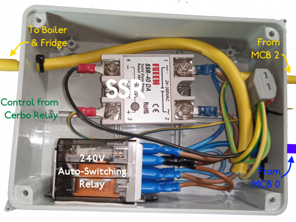
This is what the Auto Switching Relay and SSR with its cabling looks like in ‘real life.
The AC Wiring
I am making this change on my own Motorhome rather than in some lab/shed setup so it is a ‘real’ installation and accompanied with typical components that needed to be worked with.
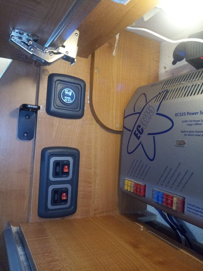
What you see in this image is a Sargent 325 PDU in my Autotrail Motorhomer. This unit has 3 MCBs with circuits going to various sockets and devices.
I only want to control the outputs to the Fridge and the Water Heater and the rest continue to be always fed by the Sargent (except the Space Heater, but that is a different topic!)
So I rewired the supply to the Fridge and Boiler to come from the Transfer Switch, but via a pair of AC Spurs. This will let me easily turn off the AV to one device and leave the other available if I wanted without crawling under the cooker or fridge to flick the switch on the devices sockets.
Very pleased with how this part of the project turned out.
The Acid Test ….
Tried out the new setup overnight
Unplugged the Fridge and plugged in a little mini-oil Rad set on low.
Disconnected the EHU around 8PM and just left the system to do its thing ….
You can see the Inverter switching itself on periodically as the heater kicks on.
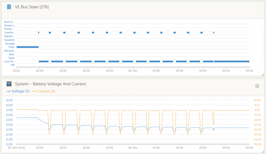
You might have noticed that around 3:30AM, the inverter comes on for a shorter time and and then does not come on again?
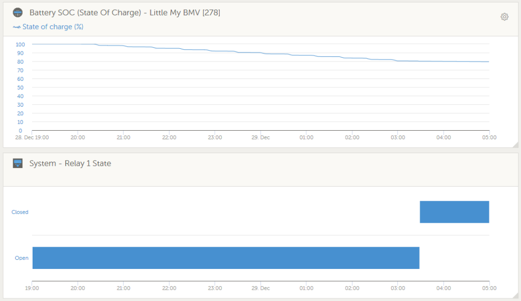
Reason for this is quite simple … The Cerbo relay that controls the SSR mentioned in the previous post was programmed to activate when the Battery State of Charge (SOC) dropped to 80%.
This relay coming on (Closing) disconnected* the SSR, thus removing power to the Mini Heater (on the Fridge socket for this test). So the AC demand disappeared and the Inverter turned itself off.
So operated exactly as planned, which is always a nice result to get!
*Just a comment. A relay coming on DISCONNECTING something may seem a strange way to use it as relays usually turn things on, not off. The reason for how this is setup is because to automate this process, I am using the Victron OS programmable feature of sending a signal to have a generator turn itself on when the batteries go low in order to recharge the batteries. So the relay activates at a low SOC to do this rather than turning off a relay at a low SOC.
The relay is fitted with both an NO and an NC connection. NO – Normally Open- gets connected when the relay is Active; NC – Normally Connected – is, well, normally connected, but gets disconnected when the relay is Active. By using the NC connection, I have the SSR connected when the Cerbo Relay is OFF (Open in above chart), and the SSR is disconnected when the Cerbo Relay turns on (shown as ‘Closed’ in the chart).
Let’s Add Extra Flexibility!
Maybe your battery is a bit lower than minimum in the Relay setup, but you will be off driving shortly or the forecast is Sun, Sun, Sun and you know the solar will be doing overtime.
In which case you might decide you can use a bit more battery power to the Fridge or Boiler. To to that you add a Countdown Timer into the mix ….
To activate the Countdown Timer, a momentary push-to-make switch makes a connection to two pins and starts the Countdown. If the Switch is pushed again whilst the Countdown is running, the timer is disconnected and the CTR is switched off (and the SSR is controlled by the Cerbo again). The timer I will be using is this one – https://amzn.to/3hrtILx
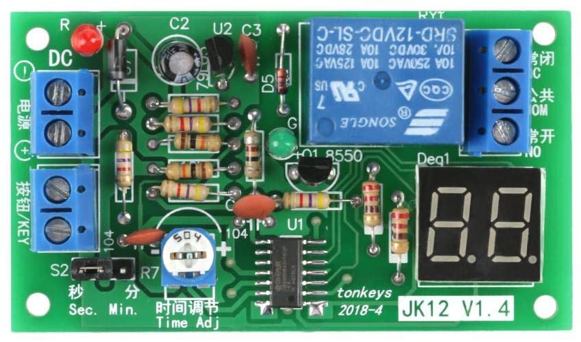
The one shown here is the only one I could find that can be set to a decent duration – upto 99 seconds or upto 99 Minutes. A 60 or 90 minute (1 or 1.5 Hr) override will work out fine I think
There are quite a few around, but most have a very limited delay duration of just a few seconds, with the odd one maging 999 Seconds (16 Minutes) and I wanted a longer countdown.
Let’s Add Extra Flexibility!
This is how the wiring looks for the Transfer Switch with the SSR Feature and Countdown Timer controlled by an SOC Relay.
If you didn’t have the Count Down Timer (CDT), the NC output of the Cerbo would go to the +ve of the SSR. But with the Timer, it now goes to the NC of the CDT Relay (lets call this the CTR). And the COM of the CTR now goes to the +ve of the SSR. Controlling the CDT works as follows:
The Delay Activate Switch is a 3-way On/Off/On switch.
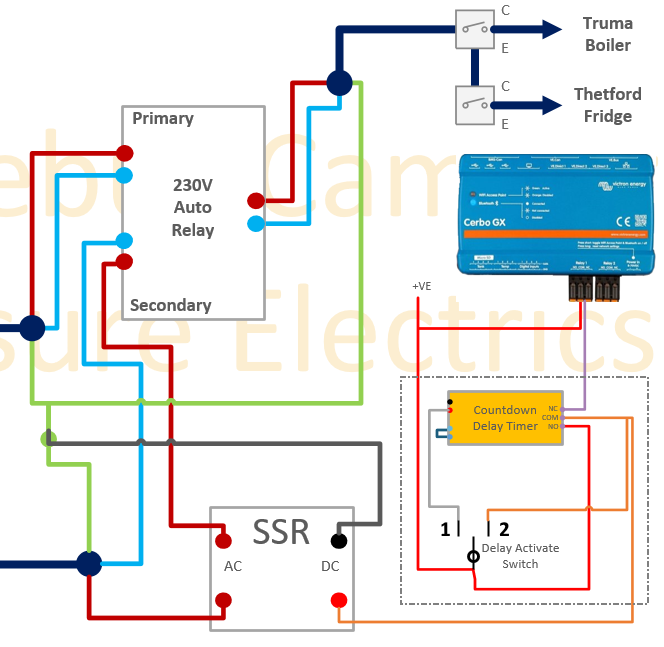
- In position 0 (Off – as shown above), the Timer (CDT) is off, which means the CDT Relay connects NC (from Cerbo) to COM (to SSR). This means the CDT is bypassed and the SSR state is solely determined by the state of the Cerbo Relay.
- In position 1 (On, switch to the left), the CDT gets power and starts its downdown. This enables the CTD Relay, which connects NO (which has a +VE signal) to COM, thus turning on the SSR. As soon as the Countdown hits zero, the CTD Relay turns off, and again the SSR is controlled by the Cerbo only.
I have set the countdown duration to 60 minutes – so as soon as the Switch is in position 1, the SSR will be force-enabled for 60 minutes and then revert to Cerbo Control. To get another 60 minutes of timer, the Switch needs to be put back to position 0 and then position 1 again.
To cancel the timer early, simply put the switch back to position 0 and leave there. - In position 2 (On, switch to the right), the CDT does not get any power and so no timer is active. However the CDT Relay COM is connected to +VE directly and as the COM is routed to the SSR, the SSR will be on all the time the switch is in position 2.
So in summary, with this switch I can (in Position 2) force the Fridge & Boiler circuits to work like the other circuits in the Motorhomer i.e. On EHU or Inverter regardless of any Battery level; or (in Position 1) work for just 60 minutes regardless of Battery level; or finally in the default (in Position 0), be controlled fully dependant on Battery level.